| Version 17 (modified by , 15 years ago) ( diff ) |
|---|
Labassert User Guide
Reference: ESA/ESTEC contract n°21166/07/NL/JK -8 Jan. 2008
Written by: Jérôme Legrand on 20 Nov. 2008
Checked by: Pierre Dissaux on 21 Nov. 2008
EUROPEAN SPACE AGENCY CONTRACT REPORT
The work described in this report was done under ESA contract. Responsibility for the contents resides in the author or organisation that prepared it.
Ellidiss Technologies :
www.ellidiss.com
24 quai de la douane, 29200 Brest, France
Tel. +33 (0) 298 451 870
1. Installation
Labassert 1.0 is available on Windows and Linux. Its installation requires no specific platform dependent procedure. The only action that may be required is to uncompress the archive with the appropriate utility if the distribution was provided as a zip or tar.gz file.
Labassert can even be run directly from a remote device, such as an USB stick, without having to install the product on the hard disk of the computer.
An uncompressed distribution of Labassert 1.0 contains the following files:
- labassert.exe: Windows executable file.
- Labassert.bin: Linux executable file.
- labassertConfiguration.xml: portable customization file for the user interface.
- examples directory: contains a few Labassert models files
- documentation directory: contains this file and the Labassert study report.
The Labassert software is a deliverable of an ESA funded study. As thus its distribution and use rules follow the General Clauses and Conditions for ESA Contracts. Please contact ESA or Ellidiss representative for further information about licensing topics.
Ellidiss Technologies can provide technical support to users of the Labassert tool. Please use the following address to send technical or commercial inquires: labassert@ellidiss.com
2. Applications Description
2.1 Launcher
The launcher is used to open the functional, the interface and the deployment view editors.
2.1.1. Screenshots

2.2 Functional View
The Functional View Editor manages the applicative functions that can be referred within the Interface View.
A Function is composed of one or several entry points called Interfaces. Each Interface may have zero or several typed Parameters.
Parameter Data Types must be loaded with the File/Load Data View menu (.aadl file).
Functional View models can be stored in separate Libraries (.lfv files).
2.2.1. Screenshots

2.2.2. File menu description
- New Library : create a new functional view.
- Open Library : load an existing functional view (.lfv extension).
- Save Library : save the current functional view.
- Save Library As : save the current functional view and specify the filename.
- Load Data View : load a data view (data type from this view is then available for parameters interface creation).
- Quit : close the application.
2.2.3. Edit Menu Description
- New Function : create a function (functions appear in “Functions” notebook).
- Delete Function : delete the selected function.
- Add Interface : add an interface to a function.
- Remove Interface : remove an interface from a function.
- New Interface : create an interface (interfaces appear in “interfaces” notebook).
- Delete Interface : delete the selected interface.
- New Parameter : add a parameter to an interface.
- Delete Parameter : remove a parameter from an interface.
2.2.4. “?” Menu Description
- About : about the Interface View Editor.
- Help : application description and accelerators available.
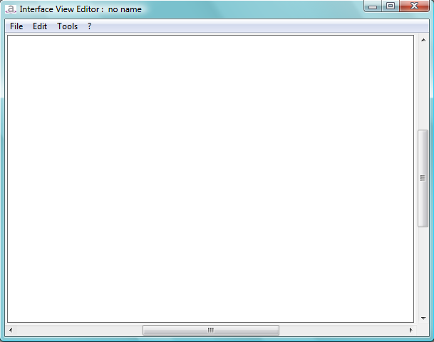
2.3 Interface View
The Interface View Editor manages the grouping and the interaction of the applicative Functions within a hierarchy of Containers.
Containers may have Provided and Required Interfaces that are associated to Function entry points at the terminal level. Lists of pre-existing Functions can be loaded with the File/Load Library menu. Provided Interfaces are characterized by a set of non functional Properties.
An AADL representation of the Interface View can be generated.
Interface View models can be stored in separate Files (.liv files).
2.3.1 Screenshots

2.3.2 File Menu Description
- New : create a new interface view.
- Load : load an existing interface view (.liv extension).
- Save : save the current interface view.
- Save As : save the current interface view and specify the filename.
- Load Functional View : load a functional view (Function from this view is then available for function creation).
- Unload Functional View : functions from the previously loaded functional view are no longer available for function creation.
- Quit : close the application.
2.3.3 Edit Menu Description
- New Container : create a Container on the work zone or in a Container.
- New Function : create a Function on the work zone or in a Container.
- New PI : create a Provided Interface on a Container or a Function.
- New RI : create a Required Interface on a Container or a Function.
- New Connection : create a connection between two objects.
- Edit Properties : if an object is selected, open a dialog box to edit its properties.
- Delete Selection : if an object is selected, remove this object from the diagram.
- Copy : if objects are selected, copy the selection.
- Paste : if objects have been copied, paste them.
- Undo : undo the last modification (remove, add or move object(s)).
- Redo : redo the last modification.
2.3.4 Tools Menu Description
- Edit Functional View : open a Functional View Editor with current Functions of the interface view (loaded and created).
- Generate Interface View : generate the AADL file of the current interface view.
- Stood :
- Set Execution Path : define the actual location of Stood executable on the system
- Open In Stood : create a Stood model and open Stood
- Generate Interface View : use Stood AADL code generator to generate the Interface View.
- Generate Concurrency View : use Stood AADL code generator and ASSERT Vertical Transformation to generate the Concurrency View.
- Navigation Panel : open the navigation panel in order to scroll and zoom the diagram.
- Option : launch Interface View Editor option dialog box.
2.3.5 “?” Menu Description
- About : about the Interface View Editor.
- Help : application description and accelerators available.
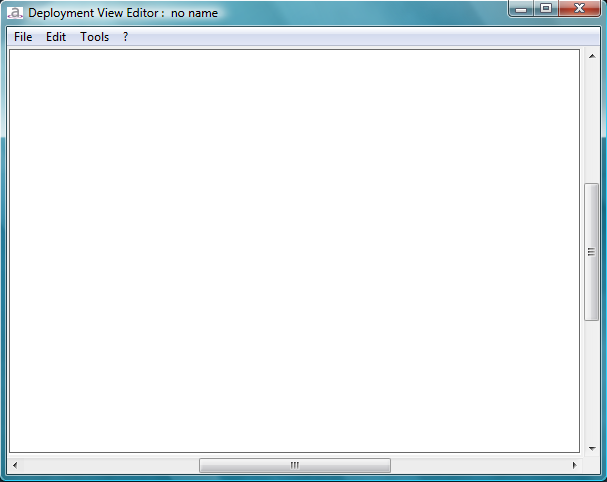
2.4 Deployment View
The Deployment View Editor manages the description of the run-time hardware and the allocation of the software elements onto it.
The hardware architecture is described in terms of Processors and Busses. Processors must contain one or several Partitions. Partitions must contain one or several applicative Functions. Available Functions must be loaded from an existing Interface View.
An AADL representation of the Deployment View can be generated.
Deployment View models can be stored in separate Files (.ldv files).
2.4.1 Screenshots

2.4.2 File Menu Description
- New : create a new diagram.
- Load : load an existing diagram (.ldv extension).
- Save : save the current diagram.
- Save As : save the current diagram and specify the filename.
- Load Interface View : load an interface view (Function from this view is then available for function creation).
- Quit : close the application.
2.4.3 Edit Menu Description
- New Processor : create a Processor on the work zone.
- New Partition : create a Partition on a Processor.
- Add Function : create a Function on a Partition (an Interface View file containing function(s) has to be open).
- New Bus : create a Bus on the work zone.
- New Processor Interface : create a Processor Interface on a Processor.
- New Connection : create a connection between a Bus and a Processor/Processor Interface.
- Edit Properties : if an object is selected, open a dialog box to edit its properties.
- Delete Selection : if an object is selected, remove this object from the diagram.
- Copy : if objects are selected, copy the selection.
- Paste : if objects have been copied, paste them.
- Undo : undo the last modification (remove, add or move object(s)).
- Redo : redo the last modification.
2.4.4 Tools Menu Description
- Generate Deployment View : generate the AADL file corresponding to the current deployment view.
- Navigation Panel : open the navigation panel in order to scroll and zoom the diagram.
- Option : launch Deployment View Editor option dialog box.
2.4.5 "?” Menu Description
- About : about the Deployment View Editor.
- Help : application description and accelerators available.
3. Tutorial
This tutorial presents a classic way of using Functional View, Interface View and Deployment View Editors.
3.1 Functional View Editor
- Launch the Functional View Editor.
- Load a Data View (File → Load Data View):
AADL representation of the Data View files must exist in the workspace. They are usually generated by the Asn2aadlPlus tool. However, a simplistic version of an AADL Data View can be created with any text editor for the purpose of the tutorial. Its contents should be the following:
PACKAGE Tutorial_Types
PUBLIC

DATA Float
END Float;

END Tutorial_Types;
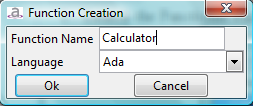
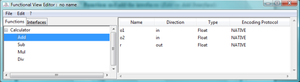
- Create a Function named “Calculator” (Edit → New Function) :

- Click on the “Interfaces” tab.
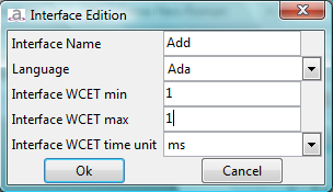
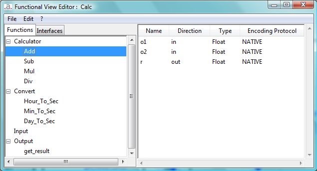
- Create 4 Interfaces named “Add”, “Sub”, “Mul” and “Div” with same attributes (Edit → New Interface) :

- For each interfaces, create 3 parameters
(Select the interface and click on Edit → New Parameter) :
- o1 : direction “in”, type “Float” and protocol “NATIVE”.
- o2 : direction “in”, type “Float” and protocol “NATIVE”.
- r : direction “out”, type “Float” and protocol “NATIVE”.

Note : the newly created parameters shall appear on the right table application.
- Click on the “Functions” tab.
- Select the “Calculator” Function and add the interfaces (Edit → Add Interface) :

- Finally, save the current library (File → Save Library) :

Note : in the save as dialog box, a default name is proposed for the file : the previously given library name with the “.lfv” extension (Calc.lfv in our example).
3.2 Interface View Editor
- Launch the Interface View Editor.
- Load the previous Functional View (File → Load Functional View) : “Calc.lfv” file.
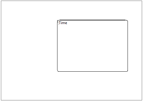
- Create a Container named “Time” (Edit → New Container or right mouse button contextual menu New Container entry) :

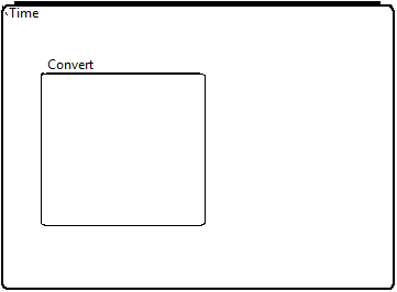
- Create a Function named “Convert” into the “Time” Container (Edit → New Function or right mouse button contextual menu New Function entry) :

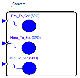
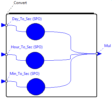
- Create 3 Provided Interfaces on the “Convert” Function (Edit → New PI or right mouse button contextual menu New PI entry) :
- Day_To_Sec : kind “sporadic”, Inter-arrival time “100”, deadline “5” and “ms” unit.
- Hour_To_Sec : kind “sporadic”, Inter-arrival time “100”, deadline “5” and “ms” unit.
- Min_To_Sec : kind “sporadic”, Inter-arrival time “100”, deadline “5” and “ms” unit.

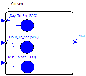
- Create 1 Required Interfaces on the “Convert” Function (Edit → New RI or right mouse button contextual menu New RI entry) :
- “Mul” : choose the operation “Mul” in the combo box.

- Connect all Provided Interface Implementation to the “Mul” Required Interface. In order to create a connection between 2 objects, you have to :
- Click on Edit → New Connection menu or right mouse button contextual menu New Connection entry or push the “shift” key (don't release the key until the connection has been created).
- Select the first object by pushing the left mouse button (don't release the button).
- And release the left mouse button on the second object.

Notes :
- A connection can be created only between item which have the same parent or have a child-parent relationship.
- There is a real time connection creation consistency check, when a connection can be created, mouse cursor turns into a crossbar.
- There is an automatic interface(s) creation facility when 2 objects are connected : in our example, a Required Interface is automatically created on the Provided Interface Implementation.
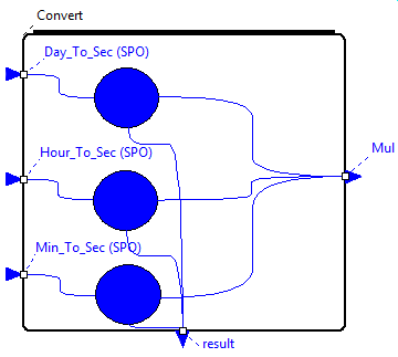
- Create 1 Required Interfaces on the “Convert” Function and connect all Provided Interface Implementation to it :
- “Result” : leave the operation field blank.

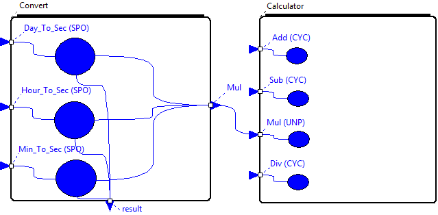
- Create a “Calculator” Function chosen from the previously loaded Functional View (choose the Function name in the creation dialog-box list) and connect the “Convert” Function “Mul” Required Interface to the “Calculator” Function “Mul” Provided Interface. Edit the “Mul” Provided Interface by double clicking on it and choose “unprotected” kind.

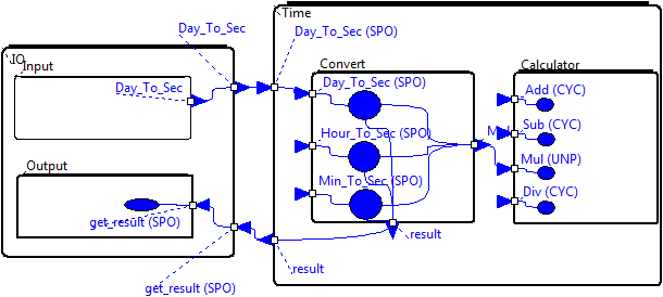
- Create a “IO” Container and in this container create 2 Functions, “Input” and “Output”.
- Create a “sporadic” Provided Interface named “get_result” on the “Output” Function.
- Connect the “Input” Function to “Day_To_Sec” Provided Interface and the “get_result” Provided Interface to the “result” Required Interface.

- Save the current interface view as “Time_Conversion.liv” (File → Save).
- Double left click on a Provided Interface Implementation or select Tools → Edit Functional View. A functional view is opened with all the functions and Function's interfaces (open and created in the Interface View) :

Note : this new library can be edited and save for further use.
15.Generate the AADL file “Time_Conversion.aadl” (Tools → Generate Interface View). You can check the consistency of the result.
3.3 Deployment View Editor
- Launch the Deployment View Editor.
- Load the previous Interface View (File → Load Interface View) : “Time_Conversion.liv” file.
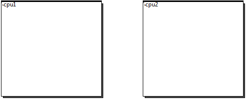
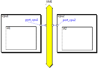
- Create 2 Processors (Edit → New Processor or right mouse button contextual menu New Processor entry) :
- cpu1 : type “pentium”, implementation name “others”, processor location “127.0.0.1” and execution platform “Native”.
- cpu2 : type “athlon”, implementation name “others”, processor location “127.0.0.2” and execution platform “Native”.

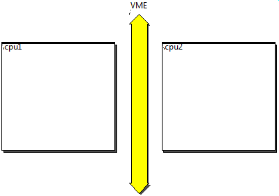
- Create a Bus named “VME” and “BSD_Sockets” transport API (Edit → New Bus or right mouse button contextual menu New Bus entry) :

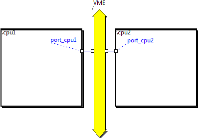
- Create 2 Processor Interfaces (Edit → New Processor Interface or right mouse button contextual menu New Processor Interface entry) :
- port_cpu1 on “cpu1” Processor : interface bus required “VME”.
- port_cpu2 on “cpu2” Processor : interface bus required “VME”.
And connect them to the bus (same process as Interface View Editor).

Note : as in Interface View Editor, automatic creation services are available. In our example, one can skip the Processor Interface creation and connect the processors to the bus.
- Create 2 Partitions (Edit → New Partition or right mouse button contextual menu New Partition entry) :
- A1 in “cpu1” Processor : type “A1”, implementation name “others” and leave port number empty.
- A2 in “cpu2” Processor : type “A2”, implementation name “others” and leave port number empty.

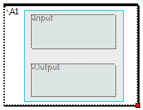
- In “A1” Partition, add “Input” and “Output” Functions (Edit → Add Function or right mouse button contextual menu Add Function entry) and in “A2” Partition, add “Convert” and “Calculator” Functions :

- Save the current deployment view as “Deployment1.ldv” (File → Save).
- Generate the AADL file “Deployment1.aadl” (Tools → Generate Deployment View). You can check the consistency of the result.
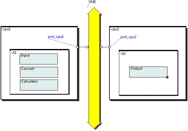
- For one Interface View, one can have several Deployment View. Remove the previously added Functions (select a Function or a group of Functions and File → Delete Selection or right mouse button contextual menu Delete Selection entry ).
Note : to select a group of items, left clic in an blank space (don't release the button), and release the left mouse button when all items you want to select are in the selection box.

- In “A1” Partition, add “Input”, “Convert” and “Calculator” Functions and in “A2” Partition, add “Output” Functions :

- Save the current deployment view as “Deployment2.ldv”.
13. Generate the AADL file “Deployment2.aadl”. You can check the consistency of the result.
Html offline version (zipped)
Ellidiss Technologies :
www.ellidiss.com
24 quai de la douane, 29200 Brest, France
Tel. +33 (0) 298 451 870

Attachments (26)
-
LabassertUserGuideTitlePagePdf.pdf
(110.5 KB
) - added by 15 years ago.
Labassert user guide title page, used for the paper output of the documentation.
- img1.png (150.5 KB ) - added by 15 years ago.
- img3.png (20.3 KB ) - added by 15 years ago.
- img4.png (28.3 KB ) - added by 15 years ago.
- img5.png (13.0 KB ) - added by 15 years ago.
- img6.png (16.5 KB ) - added by 15 years ago.
- img9.png (13.8 KB ) - added by 15 years ago.
- img10.png (1.4 KB ) - added by 15 years ago.
- img11.png (1.5 KB ) - added by 15 years ago.
- img12.png (4.0 KB ) - added by 15 years ago.
- img13.png (4.3 KB ) - added by 15 years ago.
- img14.png (5.1 KB ) - added by 15 years ago.
- img15.png (5.6 KB ) - added by 15 years ago.
- img16.png (9.0 KB ) - added by 15 years ago.
- img17.png (11.8 KB ) - added by 15 years ago.
- img18.png (30.4 KB ) - added by 15 years ago.
- img19.png (1.2 KB ) - added by 15 years ago.
- img20.png (1.8 KB ) - added by 15 years ago.
- img21.png (2.5 KB ) - added by 15 years ago.
- img22.png (3.2 KB ) - added by 15 years ago.
- img23.png (6.5 KB ) - added by 15 years ago.
- img24.png (1.9 KB ) - added by 15 years ago.
- img25.png (6.6 KB ) - added by 15 years ago.
- img7.png (25.9 KB ) - added by 15 years ago.
- img2.png (23.9 KB ) - added by 15 years ago.
- img8.png (31.2 KB ) - added by 15 years ago.
Download all attachments as: .zip